Author: Paul van der Laken

Computers decode what humans see: Generating images from brain activity

Computers decode what humans see: Generating images from brain activity

I recently got pointed towards a 2017 paper on bioRxiv that blew my mind: three researchers at the Computational Neuroscience Laboratories at Kyoto, Japan, demonstrate how they trained a deep neural network to decode human functional magnetic resonance imaging (fMRI) patterns and then generate the stimulus images.

In simple words, the scholars used sophisticated machine learning to reconstruct the photo’s their research particpants saw based on their brain activity… INSANE! The below shows the analysis workflow, and an actual reconstructed image. More reconstructions follow further on.

1.PNG
Figure 1 | Deep image reconstruction. Overview of deep image reconstruction is shown. The pixels’ values of the input image are optimized so that the DNN features of the image are similar to those decoded from fMRI activity. A deep generator network (DGN) is optionally combined with the DNN to produce natural-looking images, in which optimization is performed at the input space of the DGN. [original]
Three healthy young adults participated in two types of experiments: an image presentation experiment and an imagery experiment.

In the image presentation experiments, participants were presented with several natural images from the ImageNet database, with 40 images geometrical shapes, and with 10 images of black alphabetic characters. These visual stimuli were rear-projected onto a screen in an fMRI scanner bore. Data from each subject were collected over multiple scanning sessions spanning approximately 10 months. Images were flashed at 2 Hz for several seconds. In the imagery experiment, subjects were asked to visually imagine / remember one of 25 images of the presentation experiments. Subjects were
required to start imagining a target image after seeing some cue words.

In both experimental setups, fMRI data were collected using 3.0-Tesla Siemens MAGNETOM Verio scanner located at the Kokoro Research Center, Kyoto University.

The results, some of which I copied below, are plainly amazing.

2.PNG
Figure 2 | Seen natural image reconstructions. Images with black and gray frames show presented and reconstructed images, respectively (reconstructed from VC activity). a) Reconstructions utilizing the DGN (using DNN1–8). Three reconstructed images
correspond to reconstructions from three subjects. b) Reconstructions with and without the DGN (DNN1–8). The first, second, and third rows show presented images, reconstructions with and without the DGN, respectively. c) Reconstruction quality of seen natural images (error bars, 95% confidence interval (C.I.) across samples; three subjects pooled; chance level, 50%). d)  Reconstructions using different combinations of DNN layers (without the DGN). e) Subjective assessment of reconstructions from different combinations of DNN layers (error bars, 95% C.I. across samples) [original]
3.PNG
Figure 3 | Seen artificial shape reconstructions. Images with black and gray frames show presented and reconstructed images (DNN 1–8, without the DGN). a) Reconstructions for seen colored artificial shapes (VC activity). b, Reconstruction quality of colored artificial shapes. c) Reconstructions of colored artificial shapes obtained from multiple visual areas. d) Reconstruction quality of shape and colors for different visual areas. e) Reconstructions of alphabetical letters. f) Reconstruction quality for alphabetical letters. For b, d, f, error bars  indicate 95% C.I. across samples (three subjects pooled; chance level, 50%)  [original]
4
Supplementary Figure 2 | Other examples of natural image reconstructions obtained with the DGN. Images with black and gray frames show presented and reconstructed images, respectively (reconstructed from VC activity using all DNN layers). Three reconstructed images correspond to reconstructions from three subjects. [original]
5.PNG
Supplementary Figure 3 | Reconstructions through optimization processes. Reconstructed images obtained through the optimization processes are shown (reconstructed from VC activity of Subject 1 using all DNN layers and the DGN). Images with black and gray frames show presented and reconstructed images, respectively. [original]
There were many more examples of reconstructed images, as well as much more detailed information regarding the machine learning approach and experimental setup, so I strongly advise you check out the orginal paper.

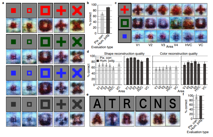
I can’t even imagine what such technology would imply for society… Proper minority report stuff here.

Here’s the abstract as an additional teaser:

Abstract

Machine learning-based analysis of human functional magnetic resonance imaging
(fMRI) patterns has enabled the visualization of perceptual content. However, it has been limited to the reconstruction with low-level image bases (Miyawaki et al., 2008; Wen et al., 2016) or to the matching to exemplars (Naselaris et al., 2009; Nishimoto et al., 2011). Recent work showed that visual cortical activity can be decoded (translated) into hierarchical features of a deep neural network (DNN) for the same input image, providing a way to make use of the information from hierarchical visual features (Horikawa & Kamitani, 2017). Here, we present a novel image reconstruction method, in which the pixel values of an image are optimized to make its DNN features similar to those decoded from human brain activity at multiple layers. We found that the generated images resembled the stimulus images (both natural images and artificial shapes) and the subjective visual content during imagery. While our model was solely trained with natural images, our method successfully generalized the reconstruction to artificial shapes, indicating that our model indeed ‘reconstructs’ or ‘generates’ images from brain activity, not simply matches to exemplars. A natural image prior introduced by another deep neural network effectively rendered semantically meaningful details to reconstructions by constraining reconstructed images to be similar to natural images. Furthermore, human judgment of reconstructions suggests the effectiveness of combining multiple DNN layers to enhance visual quality of generated images. The results suggest that hierarchical visual information in the brain can be effectively combined to reconstruct perceptual and subjective images.

Analytics in HR case study: Behind the scenes

Analytics in HR case study: Behind the scenes

Past week, Analytics in HR published a guest blog about one of my People Analytics projects which you can read here. In the blog, I explain why and how I examined the turnover of management trainees in light of the international work assignments they go on.

For the analyses, I used a statistical model called a survival analysis – also referred to as event history analysis, reliability analysis, duration analysis, time-to-event analysis, or proporational hazard models. It estimates the likelihood of an event occuring at time t, potentially as a function of certain data.

The sec version of surival analysis is a relatively easy model, requiring very little data. You can come a long way if you only have the time of observation (in this case tenure), and whether or not an event (turnover in this case) occured. For my own project, I had two organizations, so I added a source column as well (see below).

# LOAD REQUIRED PACKAGES ####
library(tidyverse)
library(ggfortify)
library(survival)

# SET PARAMETERS ####
set.seed(2)
sources = c("Organization Red","Organization Blue")
prob_leave = c(0.5, 0.5)
prob_stay = c(0.8, 0.2)
n = 60

# SIMULATE DATASETS ####
bind_rows(
  tibble(
    Tenure = sample(1:80, n*2, T),
    Source = sample(sources, n*2, T, prob_leave),
    Turnover = T
  ),
  tibble(
    Tenure = sample(1:85, n*25, T),
    Source = sample(sources, n*25, T, prob_stay),
    Turnover = F
  )
) ->
  data_surv

# RUN SURVIVAL MODEL ####
sfit <- survfit(Surv(data_surv$Tenure, event = data_surv$Turnover) ~ data_surv$Source)

# PLOT  SURVIVAL ####
autoplot(sfit, censor = F, surv.geom = 'line', surv.size = 1.5, conf.int.alpha = 0.2) +
  scale_x_continuous(breaks = seq(0, max(data_surv$Tenure), 12)) +
  coord_cartesian(xlim = c(0,72), ylim = c(0.4, 1)) +
  scale_color_manual(values = c("blue", "red")) +
  scale_fill_manual(values = c("blue", "red")) +
  theme_light() +
  theme(legend.background = element_rect(fill = "transparent"),
        legend.justification = c(0, 0),
        legend.position = c(0, 0),
        legend.text = element_text(size = 12)
        ) +
  labs(x = "Length of service", 
       y = "Percentage employed",
       title = "Survival model applied to the retention of new trainees",
       fill = "",
       color = "")
survival_plot
The resulting plot saved with ggsave, using width = 8 and height = 6.

Using the code above, you should be able to conduct a survival analysis and visualize the results for your own projects. Please do share your results!

Visualizing model uncertainty

Visualizing model uncertainty

ungeviz is a new R package by Claus Wilke, whom you may know from his amazing work and books on Data Visualization. The package name comes from the German word “Ungewissheit”, which means uncertainty. You can install the developmental version via:

devtools::install_github("clauswilke/ungeviz")

The package includes some bootstrapping functionality that, when combined with ggplot2 and gganimate, can produce some seriousy powerful visualizations. For instance, take the below piece of code:

data(BlueJays, package = "Stat2Data")

# set up bootstrapping object that generates 20 bootstraps
# and groups by variable `KnownSex`
bs <- ungeviz::bootstrapper(20, KnownSex)

ggplot(BlueJays, aes(BillLength, Head, color = KnownSex)) +
  geom_smooth(method = "lm", color = NA) +
  geom_point(alpha = 0.3) +
  # `.row` is a generated column providing a unique row number
  # to all rows in the bootstrapped data frame 
  geom_point(data = bs, aes(group = .row)) +
  geom_smooth(data = bs, method = "lm", fullrange = TRUE, se = FALSE) +
  facet_wrap(~KnownSex, scales = "free_x") +
  scale_color_manual(values = c(F = "#D55E00", M = "#0072B2"), guide = "none") +
  theme_bw() +
  transition_states(.draw, 1, 1) + 
  enter_fade() + 
  exit_fade()

Here’s what’s happening:

  • Claus loads in the BlueJays dataset, which contains some data on birds.
  • He then runs the ungezviz::bootstrapper function to generate a new dataset of bootstrapped samples.
  • Next, Claus uses ggplot2::geom_smooth(method = "lm") to run a linear model on the orginal BlueJays dataset, but does not color in the regression line (color = NA), thus showing only the confidence interval of the model.
  • Moreover, Claus uses ggplot2::geom_point(alpha = 0.3) to visualize the orginal data points, but slightly faded.
  • Subsequent, for each of the bootstrapped samples (group = .row), Claus again draws the data points (unfaded), and runs linear models while drawing only the regression line (se = FALSE).
  • Using ggplot2::facet_wrap, Claus seperates the data for BlueJays$KnownSex.
  • Using gganimate::transition_states(.draw, 1, 1), Claus prints each linear regression line to a row of the bootstrapped dataset only one second, before printing the next.

The result an astonishing GIF of the regression lines that could be fit to bootstrapped subsamples of the BlueJays data, along with their confidence interval:

One example of the practical use of ungeviz, original on its GitHub page

Another valuable use of the new package is the visualization of uncertainty from fitted models, for example as confidence strips. The below code shows the powerful combination of broom::tidy with ungeviz::stat_conf_strip to visualize effect size estimates of a linear model along with their confidence intervals.

library(broom)
#> 
#> Attaching package: 'broom'
#> The following object is masked from 'package:ungeviz':
#> 
#>     bootstrap

df_model <- lm(mpg ~ disp + hp + qsec, data = mtcars) %>%
  tidy() %>%
  filter(term != "(Intercept)")

ggplot(df_model, aes(estimate = estimate, moe = std.error, y = term)) +
  stat_conf_strip(fill = "lightblue", height = 0.8) +
  geom_point(aes(x = estimate), size = 3) +
  geom_errorbarh(aes(xmin = estimate - std.error, xmax = estimate + std.error), height = 0.5) +
  scale_alpha_identity() +
  xlim(-2, 1)
Visualizing effect size estimates with ungeviz, via its GitHub page
Very curious to see where this package develops into. What use cases can you think of?


Add a self-explantory legend to your ggplot2 boxplots

Add a self-explantory legend to your ggplot2 boxplots

Laura DeCicco found that non-R users keep asking her what her box plots exactly mean or demonstrate. In a recent blog post, she therefore breaks down the calculations into easy-to-follow chunks of code. Even better, she included the source code to make boxplots that come with a very elaborate default legend:

Chloride by month, styled.

As you can see, the above contains much more and easier to understand information than the original ggplot2 boxplot below.

ggplot2 defaults for boxplots.

Laura wrote the custom function ggplot_box_legend() (see source code below and in Laura’s blog), which uses the cowplot package to paste the explanation to the box plot. All you need to do is call the legend function just before you run your ggplot2 boxplot call.

ggplot_box_legend <- function(family = "serif"){
  
  # Create data to use in the boxplot legend:
  set.seed(100)

  sample_df <- data.frame(parameter = "test",
                        values = sample(500))

  # Extend the top whisker a bit:
  sample_df$values[1:100] <- 701:800
  # Make sure there's only 1 lower outlier:
  sample_df$values[1] <- -350
  
  # Function to calculate important values:
  ggplot2_boxplot <- function(x){
  
    quartiles <- as.numeric(quantile(x, 
                                     probs = c(0.25, 0.5, 0.75)))
    
    names(quartiles) <- c("25th percentile", 
                          "50th percentile\n(median)",
                          "75th percentile")
    
    IQR <- diff(quartiles[c(1,3)])
  
    upper_whisker <- max(x[x < (quartiles[3] + 1.5 * IQR)])
    lower_whisker <- min(x[x > (quartiles[1] - 1.5 * IQR)])
      
    upper_dots <- x[x > (quartiles[3] + 1.5*IQR)]
    lower_dots <- x[x < (quartiles[1] - 1.5*IQR)]
  
    return(list("quartiles" = quartiles,
                "25th percentile" = as.numeric(quartiles[1]),
                "50th percentile\n(median)" = as.numeric(quartiles[2]),
                "75th percentile" = as.numeric(quartiles[3]),
                "IQR" = IQR,
                "upper_whisker" = upper_whisker,
                "lower_whisker" = lower_whisker,
                "upper_dots" = upper_dots,
                "lower_dots" = lower_dots))
  }
  
  # Get those values:
  ggplot_output <- ggplot2_boxplot(sample_df$values)
  
  # Lots of text in the legend, make it smaller and consistent font:
  update_geom_defaults("text", 
                     list(size = 3, 
                          hjust = 0,
                          family = family))
  # Labels don't inherit text:
  update_geom_defaults("label", 
                     list(size = 3, 
                          hjust = 0,
                          family = family))
  
  # Create the legend:
  # The main elements of the plot (the boxplot, error bars, and count)
  # are the easy part.
  # The text describing each of those takes a lot of fiddling to
  # get the location and style just right:
  explain_plot <- ggplot() +     stat_boxplot(data = sample_df,                  aes(x = parameter, y=values),                  geom ='errorbar', width = 0.3) +     geom_boxplot(data = sample_df,                  aes(x = parameter, y=values),                   width = 0.3, fill = "lightgrey") +     geom_text(aes(x = 1, y = 950, label = "500"), hjust = 0.5) +     geom_text(aes(x = 1.17, y = 950,                   label = "Number of values"),               fontface = "bold", vjust = 0.4) +     theme_minimal(base_size = 5, base_family = family) +     geom_segment(aes(x = 2.3, xend = 2.3,                       y = ggplot_output[["25th percentile"]],                       yend = ggplot_output[["75th percentile"]])) +     geom_segment(aes(x = 1.2, xend = 2.3,                       y = ggplot_output[["25th percentile"]],                       yend = ggplot_output[["25th percentile"]])) +     geom_segment(aes(x = 1.2, xend = 2.3,                       y = ggplot_output[["75th percentile"]],                       yend = ggplot_output[["75th percentile"]])) +     geom_text(aes(x = 2.4, y = ggplot_output[["50th percentile\n(median)"]]),                label = "Interquartile\nrange", fontface = "bold",               vjust = 0.4) +     geom_text(aes(x = c(1.17,1.17),                    y = c(ggplot_output[["upper_whisker"]],                         ggplot_output[["lower_whisker"]]),                    label = c("Largest value within 1.5 times\ninterquartile range above\n75th percentile",                             "Smallest value within 1.5 times\ninterquartile range below\n25th percentile")),                   fontface = "bold", vjust = 0.9) +     geom_text(aes(x = c(1.17),                    y =  ggplot_output[["lower_dots"]],                    label = "Outside value"),                vjust = 0.5, fontface = "bold") +     geom_text(aes(x = c(1.9),                    y =  ggplot_output[["lower_dots"]],                    label = "-Value is >1.5 times and"), 
              vjust = 0.5) +
    geom_text(aes(x = 1.17, 
                  y = ggplot_output[["lower_dots"]], 
                  label = "<3 times the interquartile range\nbeyond either end of the box"), 
              vjust = 1.5) +
    geom_label(aes(x = 1.17, y = ggplot_output[["quartiles"]], 
                  label = names(ggplot_output[["quartiles"]])),
              vjust = c(0.4,0.85,0.4), 
              fill = "white", label.size = 0) +
    ylab("") + xlab("") +
    theme(axis.text = element_blank(),
          axis.ticks = element_blank(),
          panel.grid = element_blank(),
          aspect.ratio = 4/3,
          plot.title = element_text(hjust = 0.5, size = 10)) +
    coord_cartesian(xlim = c(1.4,3.1), ylim = c(-600, 900)) +
    labs(title = "EXPLANATION")

  return(explain_plot) 
  
}

ggplot_box_legend()


What to consider when choosing colors for data visualization, by DataWrapper.de

What to consider when choosing colors for data visualization, by DataWrapper.de

Lisa Charlotte Rost of DataWrapper often writes about data visualization and lately she has focused on the (im)proper use of color in visualization. In this recent blog, she gives a bunch of great tips and best practices, some of which I copied below:

color in data vis advice
Gradient colors can be great to show a pattern but, for categorical data, it is often easier to highlight the most important values with colored bars, positions (like in a dot plot) or even areas. [https://blog.datawrapper.de/colors/]
color in data vis advice
If you need more than seven colors in a chart, consider using another chart type or to group categories together. [https://blog.datawrapper.de/colors/]
color in data vis advice
Consider using the same color for the same variables, but do differentiate between categories, even across graphics. [https://blog.datawrapper.de/colors/]
color in data vis advice
Using grey for less important elements in your chart makes your highlight colors (which should be reserved for your most important data points) stick out even more.  [https://blog.datawrapper.de/colors/]
color in data vis advice
Consider color-blind people. There are many different types of color blindness: Use an online tool or Datawrapper’s automatic colorblind-check. [https://blog.datawrapper.de/colors/]
 You can find additional useful tips in the original DataWrapper blog.

Xenographics: Unusual charts and maps

Xenographics: Unusual charts and maps

Xeno.graphics is the collection of unusual charts and maps Maarten Lambrechts maintains. It’s a repository of novel, innovative, and experimental visualizations to inspire you, to fight xenographphobia, and popularize new chart types.

For instance, have you ever before heard of a time curve? These are very useful to visualize the development of a relationship over time.

temp.JPG
Time curves are based on the metaphor of folding a timeline visualization into itself so as to bring similar time points close to each other. This metaphor can be applied to any dataset where a similarity metric between temporal snapshots can be defined, thus it is largely datatype-agnostic. [https://xeno.graphics/time-curve]
The upset plot is another example of an upcoming visualization. It can demonstrate the overlap or insection in a dataset. For instance, in the social network of #rstats twitter heroes, as the below example from the Xenographics website does.

temp.JPG
Understanding relationships between sets is an important analysis task. The major challenge in this context is the combinatorial explosion of the number of set intersections if the number of sets exceeds a trivial threshold. To address this, we introduce UpSet, a novel visualization technique for the quantitative analysis of sets, their intersections, and aggregates of intersections. [https://xeno.graphics/upset-plot/]
The below necklace map is new to me too. What it does precisely is unclear to me as well.

temp
In a necklace map, the regions of the underlying two-dimensional map are projected onto intervals on a one-dimensional curve (the necklace) that surrounds the map regions. Symbols are scaled such that their area corresponds to the data of their region and placed without overlap inside the corresponding interval on the necklace. [https://xeno.graphics/necklace-map/]
There are hundreds of other interestingcharts, maps, figures, and plots, so do have a look yourself. Moreover, the xenographics collection is still growing. If you know of one that isn’t here already, please submit it. You can also expect some posts about  certain topics around xenographics.

temp.JPG